Why does my SEMG safety light grid indicate “no valid configuration”?

Why can a SEMG safety light grid not be put into operation even though the wiring is correct and a comparable device is working on the same connection? This question often arises if there is an invalid configuration on the device.

Product image of the safety light curtains hand protection
SEMG safety light grid - in the event of an invalid configuration, the device displays corresponding LED signals until the correct setup is completed.

Typical indications of this are permanently lit LEDs such as DIAG4, DIAG1, ERROR, RES and OSSD off. In this state, the safety light grid deliberately prevents operation because safety-relevant settings have not been completed completely or correctly. Such a configuration error can occur if the emitter and receiver are not set up correctly during connection or parameterization. A fully completed configuration is also mandatory in the “Safety operating mode without contactor monitoring” mode.

The image shows the explanations of the LEDs as well as key points with explanations.
Explanation of the illuminated LEDs

A structured approach is recommended for rectification:

1. reset the emitter and receiver to the factory settings.
This removes incorrect or incomplete parameters.

The illustration shows instructions for resetting the emitter to the factory settings.
Procedure for resetting the emitter to the factory settings.
The illustration shows instructions for resetting the receiver to the factory settings.
Procedure for resetting the receiver to the factory settings.

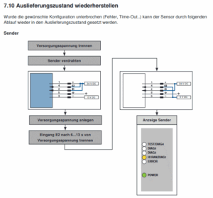
2. select the desired configuration again.

The illustration shows instructions on how to select the desired configuration.
Select the desired configuration step by step

It is important to complete the configuration so that the device recognizes the safe operating status.

The illustration shows the light curtain with an enlarged indicator of the LEDs.

3. check alignment

Incorrect alignment of the emitter and receiver is signaled via the LEDs on the receiver and should be corrected before completing the configuration.

The picture shows two squares representing the emitter and receiver. Various beams emanate from the emitter, of which only those to the receiver are marked in green and represent the correct alignment.
During installation, care must be taken to align the emitter and receiver correctly.

In practice, the SEMG safety light grid can be put back into operation properly in most cases after these steps. The LED indicators do not indicate a defect, but rather a safety-related protective function of the device.

Author

Picture of Max Mustermann

Max Mustermann

Job title