How can I combine several 1D/2D code scanners from the C5PC series via daisy chain?

We have received a request asking how several 1D/2D code scanners from the C5PC series can be set up efficiently via daisy chain.

For applications in which codes have to be scanned from different angles, the daisy chain structure offers decisive advantages. The scanners work together in a coordinated manner and can be triggered centrally.

Das Bild ist links ein Codescanner abgebildet und rechts ein Anwendungsbeispiel, bei dem vier im Kreis angeordnete Codescanner eine Dose abscannen.
Die 1D-/2D-Codescanner der C5PC-Serie lassen sich einfach zu bedienen und ermöglichen eine einfache Installation per Plug & Play.

First, the electrical connection is made: Each C5PC is supplied with power separately. The interface cables are connected in such a way that all devices in the network are accessible.

Configuration with the Device Discovery Utility

Configuration is carried out via the wenglor Device Discovery Utility:

1. device search: Find all scanners in the network; ensure that no identical IP addresses are assigned.

The picture shows the settings interface of the device and two files.
First, all available scanners in the network must be found.

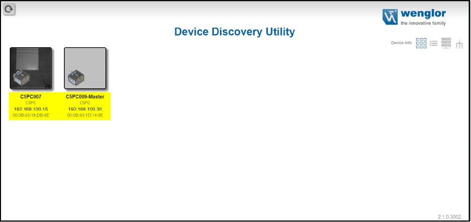
2. create a network group: Create and name a group in the software.

The image shows the Device Discovery Utility interface and the text that no groups are available.
In the second step, a new network group must be created.
The picture shows the fields that need to be filled in to create a new group.
View for creating a new group

3. add devices: Designate one device as the master (parent) and assign the others as slaves (sub).

The illustration shows the assignment as parent or child device of the two selected devices.
The master device is determined in step three.

4. open the WebLink connection: Open WebLink via the IP address of the master and set the trigger mode to serial command or external. This triggers all slaves as soon as the master is triggered.

The illustration shows the device interface, various setting functions and the camera image of the scanner.
The WebLink connection is now NC.

5. check output data: The code read is displayed in the output data – including the device name before the respective code.

The image shows the device surface of the scanner and the camera image with a Barcode.
In the fifth step, the output data is checked.

6. note: The read codes of all devices are only displayed in the output data of the master. If the output data of a slave is queried, only the data of the respective slave is displayed.

The parameters of the devices must be parameterized in the respective WebLink!

This means that a scalable, efficient and precise scanner architecture can be set up with the C5PC – ideal for applications where every perspective counts.

Our team of experts is available for further support with the setup or for individual advice on your application.

Author

Picture of Max Mustermann

Max Mustermann

Job title